
NEW 82-TON ELECTRIC LOCOMOTIVE
OF THE NORTHERN ELECTRIC RAILWAY
BY J. PAULDING EDWARDS
Electrical and Mechanical Engineer of the Company
A 53-foot electric locomotive designed by the writer has recently been placed in service on the lines of the Northern Electric Railway, a California corporation owning and operating 150 miles of third-rail electric railway in the Sacramento Valley. The locomotive, with but a few minor exceptions, is constructed entirely of steel, and was built and equipped at the company's shops at Chico, California.
BODY
The body under framing is constructed of four 12 in., 35 1/2 lb. I-beam side and center sills, running the entire length of the locomotive. The cross members are of the same size material and were accurately cut to fit the contour of the sills. Connecting angles, 6 in. x 4 in. x 1/2 in., with 3/4 in. rivets, are used to fasten them in place. The bolsters are built in place and consist of a top and bottom plate. The plates are securely riveted to two 12 in. I-beam fillers. The top bolster plate is 1 in. x 12 in., and the bottom bolster plate is 1 1/2 in. x 12 in. Both are securely riveted to the fillers and longitudinal sills by 3/4 in. rivets. The entire framing is stiffened by diagonal braces on each side of the bolsters, and the ends are braced from the center by 6 in., 12 1/2 lb. I-beams, fastened to the side sills, and by 1/2 in. x 14 in. plates which form the drawhead bumpers and end-sill contours.
body to 38 feet, eliminated one door, and moved the auxiliary equipment inside.
The side framing members, together with the thick steel sheathing, form plate trusses of each side frame; truss rods, therefore, are not required. This construction leaves the underside of the frame free for the attachment of equipment. The side framing consists of 4 in. x 3 in. x 1/2 in. angle posts connected at the top with a 4 in. x 3 in. x 1/2 inch angle plate by means of gussets and angles, and riveted with 5/8 in. rivets. The sheathing is of 3/16 in. steel plate, with butt joints, and is fastened to the side framing with 5/16 in. button-head rivets.
A plain arched roof, consisting of 3/16 in. steel plates supported on 2 1/2 in. x 2 1/2 in. x 1/4 in. angle carlines spaced 2 ft. on centers, forms an arched truss and adds materially to the strength of the body. The plates extend out over the body on the ends and sides, and afford protection from the weather and give a pleasing appearance to the roof. There is a wide wooden running board extending along the top of the roof. It is fastened to the roof by cleats which are bolted to angles riveted to the roof plates.
The first floor is nailed to 4 in. x 4 in. pine girths fastened to the side of the four sills. This floor is made of 7/8 in. vertical grain tongue and grooved pine, and is laid slightly diagonal of the car, one end being 11 in. ahead of the transverse center line. The top floor is laid crosswise, also, and is securely nailed to the first floor. A double thickness of deadening felt was placed between the two floors. The flooring on the platforms is placed diagonally, and also, is entirely separate from the main floor of the locomotive.
All the doors and sashes are made of ash and faced on the outside with No. 16 sheet steel. they are finished inside in natural color. The glass used is 3/16 in. American polished plate. The side windows are arranged to slide, and owing to their weight are hung on overhead tracks with rollers. The end sashes are stationary and secured by bolts to the window frames.
TRUCKS
The trucks were built by the Baldwin Locomotive Works, and in size are among the largest trucks ever built for this class of service. They are of the M.C.B. type, with an equalized swinging bolster carried on triple eliptical springs. They are designed to carry 55,000 lb. on center plates, and have a 90 in. wheelbase.
The axles are 7 in. in diameter at the center, with 6 1/2 in. x 11 in. journals, and are fitted with standard 36 in. M.C.B. rolled-steel wheels. The side frames are forged of 2 1/2 in. x 4 1/4 in. steel bars, and are connected to the transom channels by heavy steel castings which also support the brake levers and shoes. The brakes are inside hung and are equalized at the top of the levers by a crossbar connecting both sides and working across the top of the inside motors. The bolster is a steel casting with the side bearings and center plate cast integral. Both sides of each truck are equipped with contact shoes for the conductor rail. The shoes, which are of the slipper type operating on a top running rail, are mounted on a beam suspended from brackets cast on the bottoms of the equalizer spring seats.
MOTORS
The motor equipment is quadruple. The motors, which were designed particularly for this locomotive service, are Westinghouse No. 301-D, interpole, 550-650-volt D.C., series-wound, railway type. Forced ventilation for cooling the motors is provided by a 12-in. Sturtevant-type blower driven at 1500 r.p.m. by a 3 1/2-hp. series-wound, 550 -volt motor. The blast is conveyed through metallic conduits directly to headers immediately above the motors. From these headers it is led through the floor and through canvas tubes to the motor inlets. The nominal one-hour ratings with 550 volts at the motors are, with natural ventilation, 724 hp., and with forced ventilation, 870 hp.
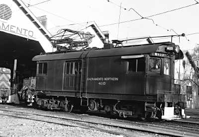
outside the Chico shops in 1950, 410 keeps company with two of the
44-ton General Electric diesels which would doom her just four years later.
W. C. Whittaker photo; Garth G. Groff collection.
CONTROL EQUIPMENT
The control equipment consists of a double set of Westinghouse unit-switch-control apparatus. Provision is made for three running points, with no external resistance in the circuit. The motors may be operated four in series, two pairs in series, or four in multiple. The pair of motors on each truck with its control forms a complete unit and may be operated as a unit, or in conjunction with the other set of motors.
The main control apparatus consisting of two line switches, two switch groups, two reversers, series-paralleling switch, change-over switch and resistance grids, is attached underneath the sills in two symmetrical groups with a conductor wires and cables run in conduit. In order to leave a clear space for all conduits and air pipes and to avoid making a number of short turns, the apparatus was suspended at a distance of from 4-6 in. below the bottom of the sills. The resistance grids were placed directly below the center sills, and were dropped below the other control equipment to give them free ventilation. Resistance grids of sufficient number and capacity have been installed to provide for the continuous operation of the locomotive at full rated capacity in any resistance control step without overheating the grids. The equipment is double-end in every respect.
The controllers are of the throttle type, and are provided with push-button control for securing the operation of a series-paralleling switch, reset of both line switches, operation of forward or rear sanders, operation of the bell, and operation of the whistle. These combinations are all secured through the use of electro-pneumatic valves, using current from the control circuit at 14 volts for their operation.
The control circuits of the series-paralleling switch interlock electrically with the master controller so that operation from one position to the other can be effected only when the controller is in the off position. This prevents the burning of propulsion circuit contacts should the buttons be depressed during the flow of current through these switches.
Direct-reading ammeters with illuminated dials are installed immediately in front of the controllers and adjacent to the air gages of the brake system. These serve to keep the operator informed at all times as to the ampere demand being made by the locomotive upon the line.
The function of the automatic change-over switch mentioned is to change the trolley and third-rail connections as required. Its operation is automatically controlled by 600-volt interlocking relays in connection with the trolley and third-rail circuits respectively.
The switchboard is in the number one end and on it are located all the switches necessary for the control of the main and auxiliary circuits. At the top of the board are the two main knife switches controlling the circuits to each pair of motors. Between these switches is a recording wattmeter. The knife switches controlling the headlights, interior lights, gage lights, pump and blower motors are located on this board. Also on this board are the governor and headlight resistances, and at the side are the control batteries.
The locomotive is equipped with Westinghouse automatic air brakes, schedule EL, which includes both the automatic and straight air features. The air brakes are arranged in two units and can be operated independently if necessary. Two 12-inch cylinders are used, each one operating on one truck independently of the other. They are both controlled, however, by the same distributing valve, which is located approximately in the center of the locomotive beneath the under framing. Compressed air is supplied by two Westinghouse D-3 compressors controlled by a single governor, but on separate circuits, so that either pump may be operated singly. The pumps are connected with two 22 x 48-in. reservoirs through radiator piping, and these reservoirs are equalized through a 1 in. pipe from which the supply is taken. The feed valves are located near the engineer's valves in the end of the locomotive.
A triple trombone whistle and locomotive-type bell are mounted on the roof in the center of the body, and are operated by air through magnetic valves which are controlled by push buttons on the master controllers. The electro-pneumatic sanders located in front of the trucks on each end are also operated by push buttons on the controllers.
PAINTING
The steel work of the body was all cleaned thoroughly by sand blasting before assembling, and also after being riveted together. It was painted with one coat of Mindura primer. The outside surface was then given one coat of glazier, four coats of surfacer and rubbed down. Four coats of Northern Electric standard orange body color were applied and finished with three coats of standard special wearing body varnish. On the inside one coat each of Mindura field and Mindura finish was applied in addition to the priming, leaving the interior with a black finish. The roof is finished the same as the interior, and all the under framing, equipment and conduits were painted black excepting the air piping and trucks. In order to readily distinguish between the air pipes in the brake system and those of the electrical equipment the former were painted a dull slate color, the latter black.
OPERATING RESULTS
The locomotive was placed in regular freight service and tests were made giving the following results: On a light run of 18 miles, with a trailing load of 13 1/2 tons, a maximum speed of 36 m.p.h. was obtained, and an average running sped of 23 1/2 m.p.h. at an average potential of 550 volts. With a trailing load of 850 1/2 tons on a 1 percent grade, with an average potential of 420 volts, maximum speed of 10 m.p.h. was reached. With a trailing load of 1145 tons on an 18-mile run, with no stops, and under ordinary conditions, an average speed of 13.3 m.p.h. was maintained, which at times reached a maximum of 24 m.p.h.
The design of this locomotive conforms, as does all the rolling stock equipment of the Northern Electric Railway, to the standards of the Master Car Builders' Association, and meets the requirements of the Interstate Commerce Commission as to the details of the safety devices.
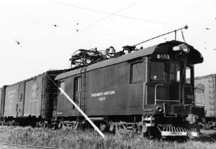
but was only 37 feet long. The NERY apparently found that 1010 was not suitable
as a dual-use motor, and dropped the express function with 1020.
Photo credited to Dick Jenevein; Garth G. Groff collection.
ADDENDUM
NERY 1010 was very successful as a locomotive, though the express motor function proved to be something of a flop. A near duplicate, NERY 1020, was built in 1915 with auxiliary equipment inside a 37-foot body, abandoning the express motor concept. With the merger in 1929, 1010 was renumbered 410. It was shortened to 38 feet in 1930, and like her little sister, had most auxiliary equipment moved inside. GE model 69Cs replaced 410's original Westinghouse 301-D motors. SNRY 410 continued to serve the SN well until scrapped in 1954.